PLC Profiling — Test Kit («건조로 #2»)
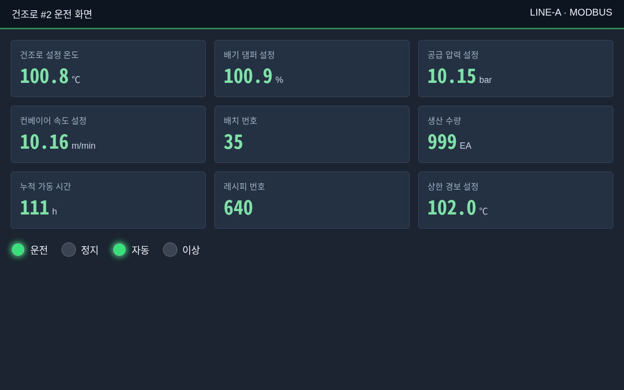
PLC profiling is a feature in which the edge scans a PLC that has no IO address list, read-only, finds the addresses actually in use, and lets you name them and register them as tags. The test kit on this page lets you try that flow from start to finish without real equipment — a Modbus TCP simulator that mimics a fictional «건조로 #2» (Drying Oven #2), plus an HMI screen photo and a PLC comment file that match its values.
PLC profiling has not been officially released yet, so it only appears in test builds that include it. You open it with the chip icon in the screen header, and it is visible only when AI is configured. For an introduction to the feature, see the «⑥ Connects even without an address list» page of the Edge proposal.
Download the Kit
| File | What | Download |
|---|---|---|
| HMI screen photo | Fictional HMI «건조로 #2 운전 화면» (Drying Oven #2 operation screen, 1280×800). Setpoints, production count and lamps match the simulator values | hmi-dryer2.png |
| PLC comments | Example PLC comment export. Modicon addresses (4xxxx · 3xxxx · 0xxxx · 1xxxx, counted from 1), UTF-8, 23 lines | dryer2-comments.csv |
| Simulator | Modbus TCP simulator whose values match the two files above. Uses only the Python 3 standard library and is read-only | dryer2_sim.py |
The photo and comments are optional attachments. Without them, default names are generated from the scan results alone — if you attach them, AI uses them as evidence to suggest tag names, descriptions and units.
Run the Simulator
python3 dryer2_sim.py 5020
- If you omit the port, it is
5020. Once running, it printsdryer2 simulator listening on :5020. - If you run it on the same host as the edge, the IP to enter in the edge is
127.0.0.1(the edge container uses the host network). If you run it on another PC, enter that PC's IP. - On another PC, you may need to open
5020/tcpin that PC's firewall. - Any Unit ID is accepted.
Values the Simulator Serves
Addresses are given both as Modbus protocol addresses (from 0) and in Modicon notation (from 1). The comment CSV uses Modicon notation.
| Area · Address | Modicon | Meaning | Value |
|---|---|---|---|
| holding 0 | 40001 | Oven current temperature (×0.1 ℃) | Moves between 99.0~102.0 |
| holding 1 | 40002 | Exhaust damper current opening (×0.1 %) | Moves |
| holding 2 | 40003 | Batch number | 35 (fixed) |
| holding 3 | 40004 | Production counter | +1 every 3 seconds |
| holding 4 | 40005 | Cumulative run time (h) | 111 (fixed) |
| holding 5 | 40006 | Recipe number | 640 (fixed) |
| holding 10 | 40011 | Oven temperature setpoint (×0.1 ℃) | 1008 → 100.8 ℃ |
| holding 11 | 40012 | Exhaust damper setpoint (×0.1 %) | 1009 → 100.9 % |
| holding 12 | 40013 | Supply pressure setpoint (×0.01 bar) | 1015 → 10.15 bar |
| holding 13 | 40014 | Conveyor speed setpoint (×0.01 m/min) | 1016 → 10.16 m/min |
| holding 14 | 40015 | High alarm setpoint (×0.1 ℃) | 1020 → 102.0 ℃ |
| holding 20–21 | 40021–40022 | Supply pressure current value, FLOAT32 high word first | Moves between 10.0~10.3 bar |
| input 0 | 30001 | Production count display (EA) | 999 |
| input 1 | 30002 | Run time display (h) | 111 |
| coil 0~3 | 00001~00004 | Run · Stop · Auto · Fault lamps | 1 · 0 · 1 · 0 |
| discrete 0 | 10001 | Door closed | 1 |
| discrete 1 | 10002 | Emergency stop pressed | 0 |
| discrete 2 | 10003 | Burner flame detected | Blinks every 5 seconds |
- All four areas serve addresses 0~1999; addresses not in the table above are 0.
- Addresses 2000 and above are answered as «no such address» (Modbus exception 02) — this is where the scan's boundary search finds the end.
- Write requests (function codes 5 · 6 · 15 · 16) are rejected with exception 01.
Test Procedure
- Open PLC profiling in the edge screen header.
- Choose Enter new PLC info and enter the name «건조로 #2», a description (required), protocol Modbus, the IP decided above and port
5020. - Set the scan time to 5 minutes.
- Attach the kit's HMI photo and comment CSV (optional).
- Click Start.
- When the scan finishes, click Generate names with AI.
- On the ④ Confirm · Register screen, review the accuracy and evidence, check the correct ones and register them.
Expected Results
- The photo's setpoints 100.8 · 100.9 · 10.15 · 10.16 · 102.0 are paired with 40011~40015.
- The photo's 35 · 640 · 111 · 999 are also paired with their respective addresses.
- The photo's lamps (Run · Stop · Auto · Fault) are paired with coils 00001~00004.
49001in the comment CSV is outside the scan area and is discarded — this is expected.- If the photo has no capture time (EXIF), it is compared with the values at upload time. So moving values such as temperature, opening and pressure may not match — fixed values and setpoints are the basis for pairing.
This kit is for testing, not a PLC in actual operation. The simulator rejects writes (read-only) and accepts connections on all network addresses, so run it only on a test network and stop it when testing is done.
Protocol-Specific Prerequisites and Constraints
Check the following before scanning a real PLC. When you choose a protocol on the start screen, the edge screen also shows the same information above the target area.
Common
- On a PLC that limits the number of concurrent connections, the scan connection may be refused if an existing collection is already using the connection. In that case the scan stops with the reason "second connection refused".
- The PLC port must be open in the firewall.
Siemens S7 (1200/1500)
- CPU Properties › Protection & Security › Connection mechanisms › «Permit access with PUT/GET communication from remote partner» must be enabled for M · I · Q to be read as well. If the protection level is «No access (complete protection)», nothing can be read either.
- DBs created with «Optimized block access» in TIA Portal cannot be read by address and are left out of the scan (this is common on 1200/1500 in the field). Turn off «Optimized block access» for that DB and download it again to make it readable.
Mitsubishi
- The MC protocol (SLMP) port must be open in the PLC's Ethernet settings, and the communication data code must be «Binary».
- FX3 needs the MC protocol setting on its Ethernet adapter (FX3U-ENET, etc.), and the A series needs 1E frame communication on its Ethernet module.
- ZR (extended file registers) is not included in the default scan area.
LS
- The FEnet module's «XGT dedicated protocol» (default port
2004) must be enabled, and the edge must be in the list of IPs allowed to connect. - On XGI / XEC, variables that have only a name and no direct address (
%MW·%MX, etc.) cannot be read by address and are left out of the scan.
Modbus
- What is at which address differs from device to device. If the Unit ID is wrong, nothing is read.
- Going through an RTU-TCP gateway is very slow, so set the scan time to 30 minutes or more.